

| Citation: |
Li Huang, Jia-le Kang, Xiao-dong Shen, Jian-ye Sun, Qing-guo Meng, Qiang Chen, Gao-wei Hu, Chang-ling Liu, Neng-you Wu, 2022. Experimental investigation of hydrate formation in water-dominated pipeline and its influential factors, China Geology, 5, 310-321. doi: 10.31035/cg2022015

|
Experimental investigation of hydrate formation in water-dominated pipeline and its influential factors
-
Abstract
Blockage in water-dominated flow pipelines due to hydrate reformation has been suggested as a potential safety issue during the hydrate production. In this work, flow velocity-dependent hydrate formation features are investigated in a fluid circulation system with a total length of 39 m. A 9-m section pipe is transparent consisted of two complete rectangular loops. By means of pressurization with gas-saturated water, the system can gradually reach the equilibrium conditions. The result shows that the hydrates are delayed to appear as floccules or thin films covering the methane bubbles. When the circulation velocity is below 750 rpm, hydrate is finally deposited as a “hydrate bed” at upmost of inner wall, narrowing the flow channel of the pipeline. Nevertheless, no plugging is observed during all the experimental runs. The five stages of hydrate deposition are proposed based on the experimental results. It is also revealed that a higher driving pressure is needed at a lower flow rate. The driving force of hydrate formation from gas and water obtained by melting hydrate is higher than that from fresh water with no previous hydrate history. The authors hope that this work will be beneficial for the flow assurance of the following oceanic field hydrate recovery trials.
-

-
References
Aman ZM, Leith W J, Grasso G A, Sloan ED, Sum AK, Koh CA. 2013. Adhesion force between cyclopentane hydrate and mineral surfaces. Langmuir:the ACS Journal of Surfaces and Colloids, 29(50), 15551–15557. doi: 10.1021/la403489q. Andersson V and Gudmundsson JS. 2006. Flow properties of hydrate-in-water slurries. Annals New York Academy of Sciences, 912(1), 322–329. doi: 10.1111/j.1749-6632.2000.tb06786.x. Boxall J, Davies SR, Koh CA, Sloan ED. 2009. Prediction when and where hydrate plugs form in oil-dominated flowlines. SPE Projects, Facilities and Construction, 4 (03), 80‒86. doi: 10.2118/129538-PA. Chen J, Chen GJ, Yuan Q, Deng B, Tao LM, Li CH, Xiao SX, Jiang JH, Li X, Li JY. 2019. Insights into induction time and agglomeration of methane hydrate formation in diesel oil dominated dispersed systems. Energy, 170, 604–610. doi: 10.1016/j.energy.2018.12.138. Davies SR, Boxall JA, Dieker LE, Sum AK, Koh CA, Sloan ED, Creek JL, Xu ZG. 2010. Predicting hydrate plug formation in oil-dominated flowlines. Journal of Petroleum Science and Engineering, 72 (3‒4), 302‒309. doi:10.1016/j.petrol.2010.03.031 Duan ZH, Moller N, Greenberg J, Weare JH. 1992. An equation of state for the CH4-CO2-H2O system: I. pure systems from 0 to 1000℃ and 0 to 8000 bar. Geochimica et Cosmochimica Acta, 56(7), 2605–2617. doi: 10.1016/0016-7037(92)90347-L. Duan ZH, Mao SD. 2006. A thermodynamic model for calculating methane solubility, density and gas phase composition of methane-bearing aqueous fluids from 273 to 523 K and from 1 to 2000 bar. Geochim. Cosmochim. Acta, 70(13), 3369–3386. doi: 10.1016/j.gca.2006.03.018. Gong J, Shi BH, Lu XF. 2013. Gas hydrate formation and hydrate slurry flow in multiphase transportation system. Journal of China University of Petroleum, 37(5), 163–180. doi: 10.3969/j.issn.1673-5005.2013.05.023. Hill T, Johnson T, Nicol HV. 2010. Steady-state, and interrupted, production through a deep water black oil system. In:Proceedings of Seventh North American Conference on Multiphase Technology, Canada, 21–37. Hiroshi Ohno, Robin Susilo, Raimond Gordienko, John Ripmeester, Virginia Walker. 2010. Interaction of antifreeze proteins with hydrocarbon hydrates. Chemistry A European Journal, 16(34), 10409–10417. doi: 10.1002/chem.200903201. Joshi SV, Grasso GA, Lafond PG, Rao I, Webb E, Zerpa LE, Sloan ED, Koh, CA, Sum AK. 2013. Experimental flowloop investigations of gas hydrate formation in high water cut systems. Chemical Engineering Science, 97(7), 198–209. doi: 10.1016/j.ces.2013.04.019. Konno Y, Fuji T, Sato A, Akamine K, Naiki M, Masuda Y, Yamamoto K, Nagao J. 2017. Key findings of the world’s first offshore methane hydrate production test off the coast of Japan: Toward future commercial production. Energy, 31(3), 2607–2616. doi: 10.1021/acs.energyfuels.6b03143. Kauffeld M, Kawaji M, Egolf P. 2005. Handbook on ice slurries-fundamentals and engineering. Paris, France, International Institute of Refrigeration, 1‒89. Li CJ, Huang T, Jia WL. 2016. A review of natural gas hydrates and its pipeline transportation technologies in deep water. Chinese Science Bulletin, 61(22), 2449–2462. doi: 10.1360/N972015-01344. Lim J, Kim E, Seo Y. 2016. Dual inhibition effects of diamines on the formation of methane gas hydrate and their significance for natural gas production and transportation. Energy Conversion and Management, 124, 578–586. doi: 10.1016/j.enconman.2016.07.054. Matsuzawa M, Terao Y, Hay B, Winstrom L, Duncan M, Ayling I. 2014. A completion system application for the world’s first marine hydrate production test. In:Proceedings of Offshore Technology Conference, Houston, USA,2778–2789. Moridis GJ. 2003. Numerical studies of gas production from methane hydrates. SPE Journal, 8(4), 359–370. doi: 10.2118/75691-MS. Palermo T, Riviere L, Boireau C. 2017. Capex savings might raise flow assurance challenges. Proceedings of 9th International Conference on Gas Hydrates, Denvor, Colorado USA, 275‒280. Rao I, Koh CA, Sloan ED, Sum AK. 2013. Gas hydrate deposition on a cold surface in water-saturated gas systems. Industrial and Engineering Chemistry Research, 52(18), 6262–6269. doi: 10.1021/ie400493a. Sloan ED, Koh CA. 2008. Clathrate hydrates of natural gases, third edition. New York, CRC Press, 189‒211. Srivastava V, Dapena JA, Charlton TB. 2017. Effect of particle concentration and size distribution on hydrate bedding and plugging mechanisms. Proceedings of 9th International Conference on Gas Hydrates, Denvor, Colorado USA, 731‒742. Sum AK, Koh CA, Sloan ED. 2009. Clathrate hydrates: from laboratory science to engineering practice. Industrial and engineering chemistry research, 48(16), 7457–7465. doi: 10.1021/ie900679m. Sakurai S, Nakatsuka Y, Edwards TJ, Hoskin BJ, Manning DK. 2014. An experimental study for flow assurance of the methane hydrate production test system. In:Proceedings of Offshore Technology Conference. Houston, Texas, USA,237–245. Shi BH, Gong J, Sun CY, Zhao JK, Ding Y, Chen GJ. 2011. Anward and outward natural gas hydrates growth shell model considering intrinsic kinetics, mass and heat transfer. Chemical Engineering Journal, 171(3), 1308–1316. doi: 10.1016/j.cej.2011.05.029. Sowa Barbara and Maeda Nobuo. 2015. Statistical study of the memory effect in model natural gas hydrate systems. Journal of Physical Chemistry A, 119(44), 10784–10790. doi: 10.1021/acs.jpca.5b07308. Turner D, Grasso G. 2017. Hydrate blockage-limiting mechanisms that support cold transient operation. In:Proceedings of Offshore Technology Conference. Houston, Texas, USA,1123–1128. Turner D. 2005. Clathrate Hydrate Formation in Water-in-Oil Dispersions. Denvor, Colorado, USA, Colorado School of Mines, Ph. D thesis, 1‒230. Tang CP, Zhao XY, Li DL, He Y, Shen XD, Liang DQ. 2017. Investigation of the flow characteristics of methane hydrate slurries with low flow rates. Energies, 10(1), 145–160. doi: 10.3390/en10010145. Turner DJ, Miller KT, Sloan ED. 2009. Direct conversion of water droplets to methane hydrate in crude oil. Chemical Engineering Science, 64(23), 5066–5072. doi: 10.1016/j.ces.2009.08.013. Uchida T, Yamazaki K, Gohara K. 2016. Gas nanobubbles as nucleation acceleration in the gas-hydrate memory effect. Journal of Physical Chemistry C, 120(47), 26620–26629. doi: 10.1021/acs.jpcc.6b07995. Wang WC, Chen P, Li YX, Liu HH, Zhang QD. 2014. Flow and deposition characteristics of natural gas hydrate in pipelines. Natural Gas Industry, 34(2), 99–104. doi: 10.3787/j.issn.1000-0976.2014.02.016. Yamamoto K, Kanno T, Wang XX, Tamaki M, Fuji T, Chee SS, Wang XW, Pimenov V, Shako V. 2017. Thermal responses of a gas hydrate-bearing sediment to a depressurization operation. RSC Advances, 7(10), 5554–5577. doi: 10.1039/C6RA26487E. Zerpa LE, Sloan ED, Sum AK, Koh CA. 2012. Overview of CSMHyK: A transient hydrate formation model. Journal of Petroleum Science and Engineering, 98‒99, 122‒129. doi:10.1016/j.petrol.2012.08.017 Zhao JF, Wang CJ, Yang MJ, Liu WG, Xu K, Liu Y, Song YC. 2015. Existence of a memory effect between hydrates with different structures (I, II, and H). Journal of Natural Gas Science and Engineering, 26, 330–335. doi: 10.1016/j.jngse.2015.06.031. -
Access History

Figures(12)
Tables(1)

Export File
Citation
Li Huang, Jia-le Kang, Xiao-dong Shen, Jian-ye Sun, Qing-guo Meng, Qiang Chen, Gao-wei Hu, Chang-ling Liu, Neng-you Wu, 2022. Experimental investigation of hydrate formation in water-dominated pipeline and its influential factors, China Geology, 5, 310-321. doi: 10.31035/cg2022015
Format
Content
 DownLoad:


-
Figure 1.
Schematic of the 39-m high-pressure flowloop QIMG_TFA. Main part is a 9-m transparent pipe with two complete rectangular loops. Point 2 and 4 are cambered corners, and Point 5 and 7 are perpendicular corners. The colorful piston-container is 2.1 L with lower part is highlighted in orange color.
-
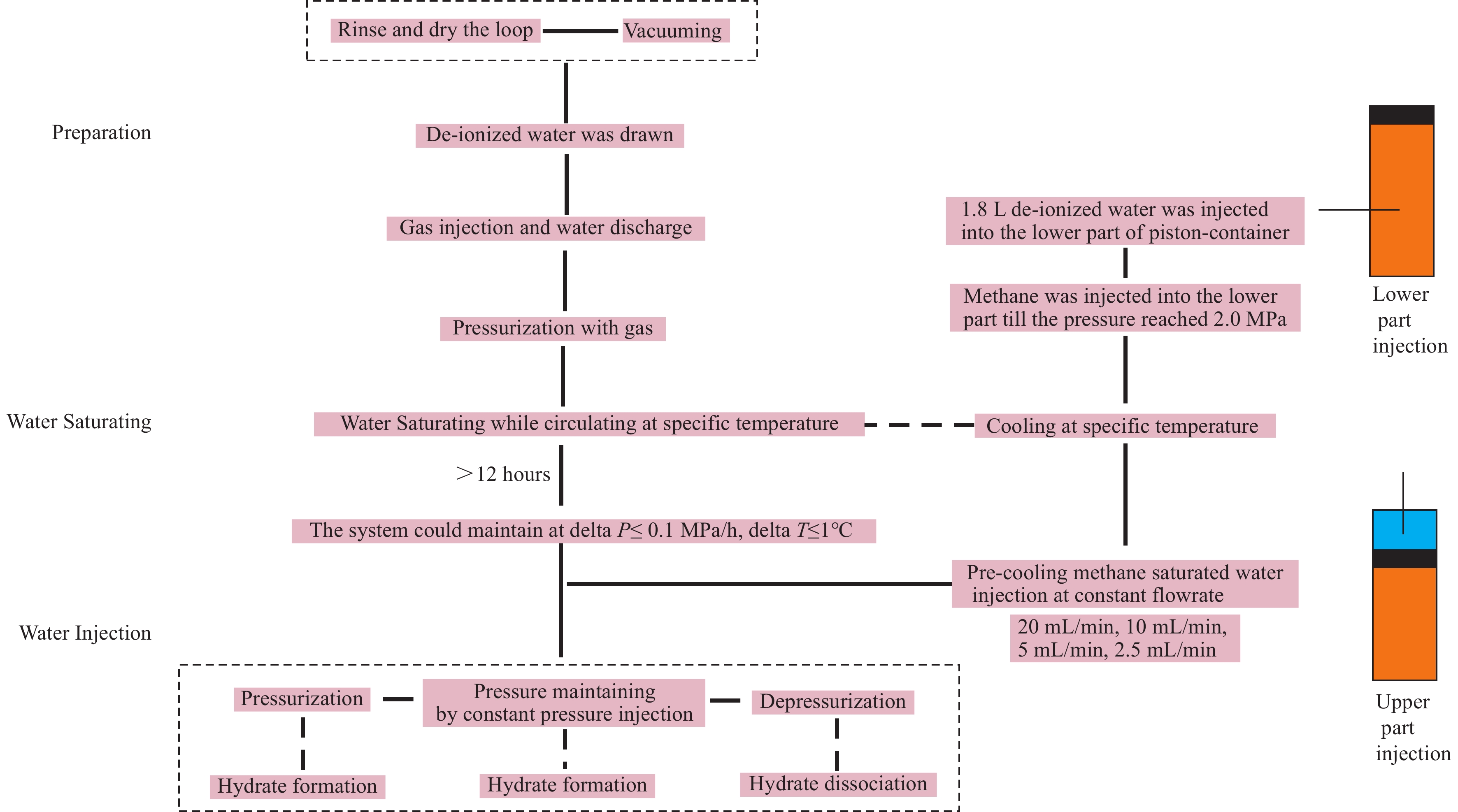
Figure 2.
The flowsheet of the whole experiment procedure.
-
Figure 3.
Variation of the temperature and pressure in the flowloop during the process of the methane-saturated water injection. Note: The three temperatures and one injection rate are both referring to left y-axis, which just the same value but different units.
-
Figure 4.
The images captured by the high-speed video camera at different moments. a1-3: the pressure in the system has not reached the equilibrium pressure and no gas hydrate can be observed; b1-3: the moment when the pressure increasing rate begins to decrease and some small hydrate particles are captured sticking in the wall.
-
Figure 5.
The formed hydrates intermittently stick to the inner wall of loops and slough off due to the flushing of water flow. The yellow circle highlighted the formed hydrates and their locations are moving and no hydrates can be seen in (5)-(6).
-
Figure 6.
The hydrate film between the gas bubbles captured by the high-speed video camera during the process of continuous gas-saturated water injection. The shape of the filmed hydrate is irregular and the gas bubbles cannot be integrated in the mixed flow.
-
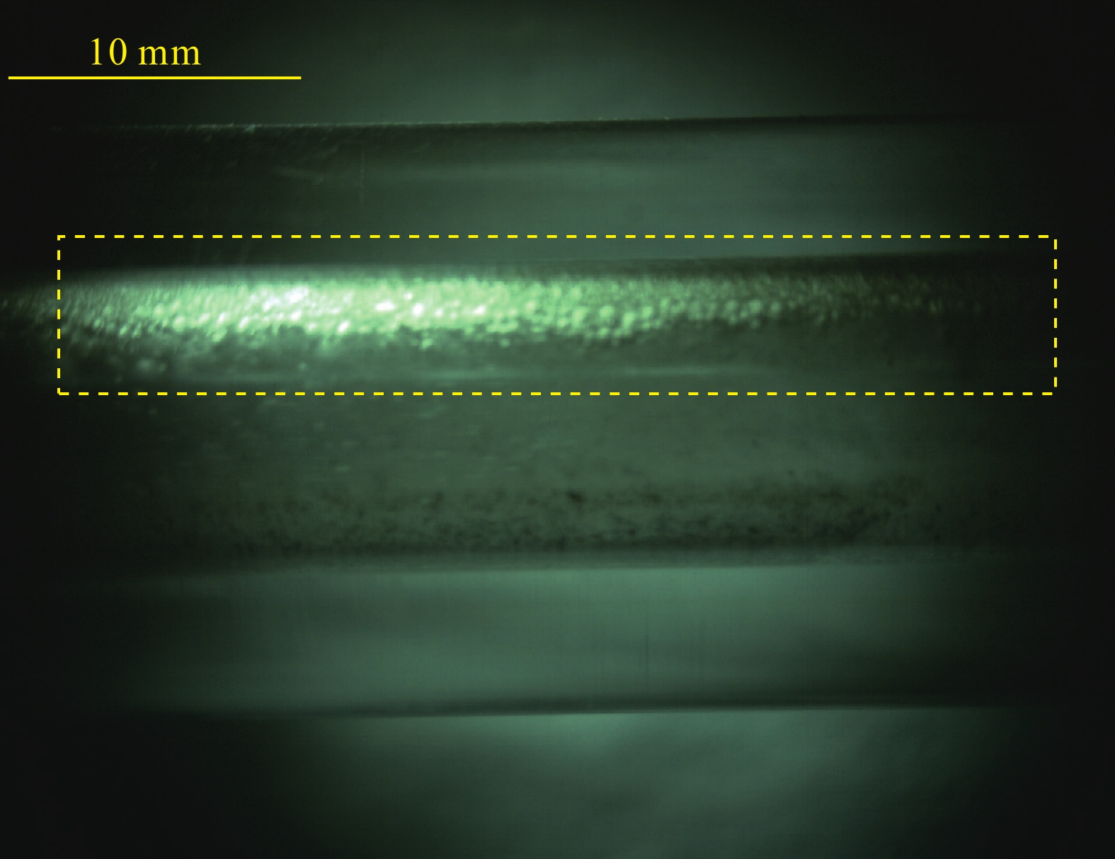
Figure 7.
A deposited hydrate bed is captured to stick to the upper inner wall when the system pressure reaches 5.0 MPa. This hydrate bed is as the same as that in Fig. 9, which are located in the two visual windows in the system.
-
Figure 8.
Hydrates are captured to intermittently accumulated in the right cambered corner. The hydrates are sticked at the different locations during the flow in figs (a), (b), (d), (e) and (f). There is no hydrate captured in fig (c).
-
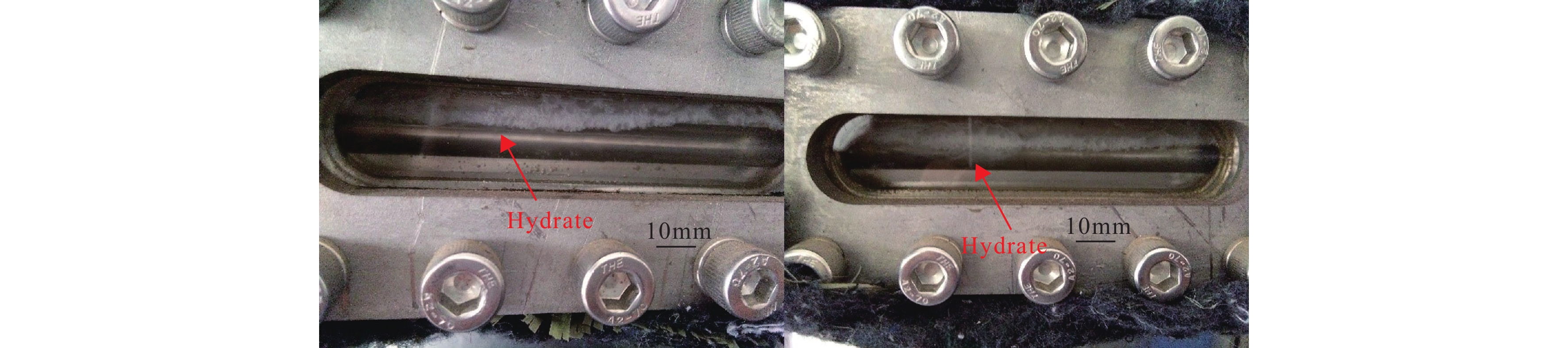
Figure 9.
Some hydrates deposited at the upper inner wall of the pipe through the visual windows. The two visible windows located at the inlet and outlet of the coiler pipe in the whole apparatus.
-
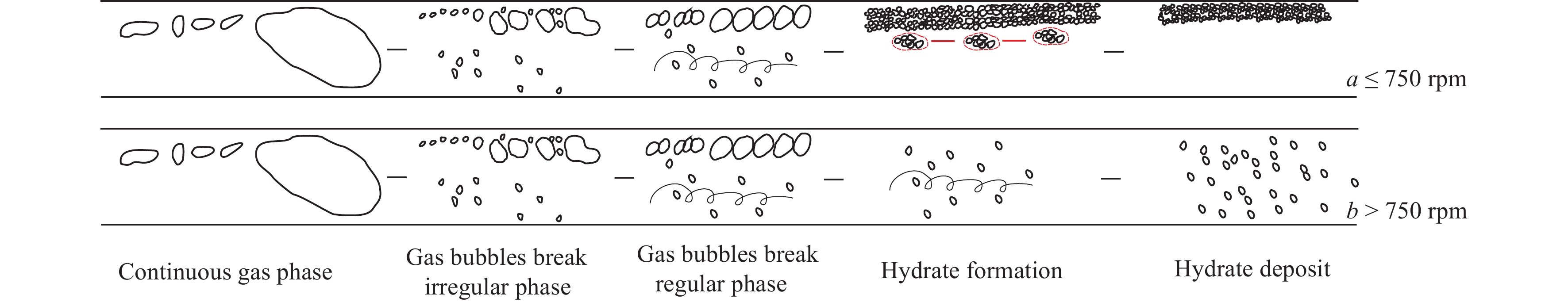
Figure 10.
Schematic of whole process of hydrate formation and deposition at different scenarios. When the circulation velocity is lower than 750 rpm, the five stages are (1) Continuous gas phase, in which the methane bubbles are normally big. (2) Gas bubbles break, and the methane bubbles normally show irregular pattern in this period. (3) Gas bubbles break, in this period the methane bubbles are continuously broken and show relatively uniform. (4) Hydrate formation, it is early hydrate bedding formation stage, and some hydrate clusters are observed moving along the lower bedding layer. (5) Hydrate deposit stage, in this stage no moving hydrate can be observed and the flow channel is narrowed. When the circulation velocity is higher than 750 rpm, there are still five stages division and the first three stages are the same. However, in the forth stage, the formed hydrates are evenly distributed in the mixture flow. And in the fifth stage, the formed hydrates are increasing and no hydrate bed was observed, and the flow channel can maintain the same.
-
Figure 11.
Flowrate variation at the entrance of the transparent flowloop.
-
Figure 12.
The hydrate formation driving pressure at different circulation velocity systems.